
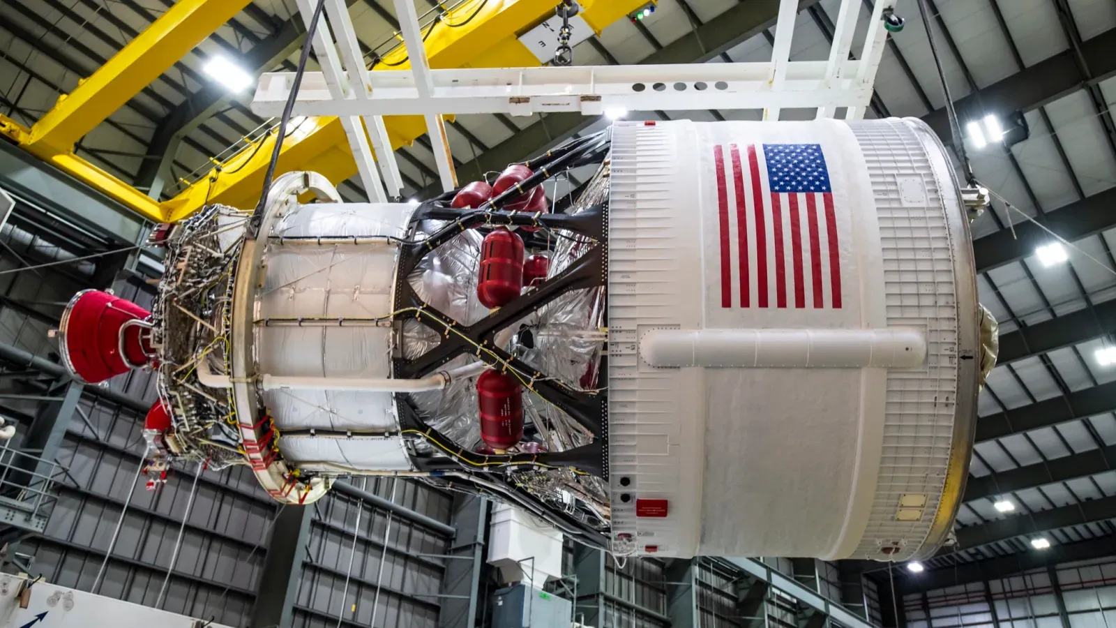
Liquid hydrogen upper stage rocket engines burn super-cold liquid hydrogen and liquid oxygen in a high-pressure combustion chamber and accelerate the resulting superheated water vapor through a wide, bell-shaped vacuum nozzle. Most upper-stage hydrogen engines run on an expander cycle, routing cryogenic liquid hydrogen through thin metal channels in the combustion chamber walls to keep the chamber from melting while using that absorbed heat to turn the liquid fuel into a high-pressure gas that spins the engine’s turbopumps. That heated hydrogen gas then flows directly into the main combustion chamber to burn with liquid oxygen, converting thermal energy into exhaust velocity without wasting propellant.
Why do upper stages use liquid hydrogen and liquid oxygen?
Once a rocket sheds its heavy first-stage booster and climbs above the dense lower atmosphere, raw liftoff thrust matters far less than propellant mass efficiency. Aerospace engineers measure that fuel efficiency as specific impulse, which indicates how many seconds one pound of propellant can produce one pound of thrust. Pairing liquid hydrogen fuel with liquid oxygen oxidizer delivers the highest specific impulse of any chemical rocket propellant combination in operational service, reaching 444.4 to 465.5 seconds in a vacuum on variants of the Aerojet Rocketdyne RL10 engine, according to NASA Glenn Research Center documentation (2014) and manufacturer specifications (2026).
That efficiency comes down to molecular weight. Because hydrogen is the lightest element on the periodic table, burning it with oxygen produces superheated water vapor mixed with unburned hydrogen gas that accelerates through a nozzle to exhaust velocities up to 4.565 kilometers per second (Wikipedia, 2026). High exhaust velocity lets a lighter upper stage impart a much larger velocity change to a spacecraft, whether the mission is injecting heavy communications satellites into high-energy geostationary transfer orbits or sending robotic probes toward outer planets.
Working with hydrogen requires extreme thermal engineering. Liquid hydrogen must be stored below its boiling point of -423 degrees Fahrenheit (-252.8 degrees Celsius, or 20 Kelvin) and has a very low liquid density (Everyday Astronaut, 2023; NASA, 2026). Even a tiny amount of ambient heat causes the liquid to boil into gas, which is why upper stages need insulated tanks and active thermal control from launchpad loading through orbital flight.
How does the expander cycle power a liquid hydrogen upper stage rocket engine?
First-stage booster engines typically burn a portion of their fuel and oxidizer in a small secondary combustion chamber, called a preburner or gas generator, just to create hot gas to spin their propellant pumps. Most liquid hydrogen upper stage rocket engines skip that separate burner altogether and use a closed expander cycle powered entirely by waste heat from the main combustion chamber, as documented by NASA Lewis Research Center propulsion modeling (1995) and the European Space Agency (2021).
Inside the main combustion chamber, burning hydrogen and oxygen reaches temperatures near 6,000 degrees Fahrenheit (3,315 degrees Celsius), well above the melting point of stainless steel or copper alloys (Aircraft Engine Historical Society, 2024). To keep the chamber intact, engineers use regenerative cooling, pumping cryogenic liquid hydrogen through hundreds of thin-walled tubes or milled channels that form the inner walls of the chamber and nozzle. As the liquid hydrogen absorbs heat through the metal wall, it changes phase into a warm, high-pressure gas and expands rapidly.
That expanding gas is routed out of the top of the cooling jacket and directed across the blades of a turbine near room temperature (Wikipedia, 2026; Note.com Aerospace Summary, 2024). The spinning turbine drives the centrifugal pumps that pull fresh liquid hydrogen and liquid oxygen out of the propellant tanks. In a closed expander cycle, 100 percent of the hydrogen gas exiting the turbine flows straight to the injector face to mix and burn with liquid oxygen in the main chamber.
In NASA’s classic RL10A-3-3A configuration, first flown on the RL10 family that entered service in November 1963 (L3Harris Technologies, 2023), the thermodynamic loop operates with exact mechanical tolerances:
- Cryogenic liquid hydrogen enters the two-stage centrifugal fuel pump at 38.5 degrees Rankine (-421.2 degrees Fahrenheit) and a pressure of 29.8 pounds per square inch absolute, flowing at 6.2 pounds per second (NASA, 2014).
- The fuel flows through a cooling jacket made of 360 silver-brazed 347SS stainless-steel tubes (180 short single-tapered tubes and 180 long double-tapered tubes) in a pass-and-a-half path down to the nozzle exit and back up the chamber wall (ResearchGate / NASA Contractor Study, 2024).
- Expanding hydrogen gas drives the main turbine, spinning the fuel pump at 30,000 rpm while turning a gearbox connected to the liquid oxygen pump at 12,000 rpm (NASA, 1995).
- The oxygen pump feeds 31.0 pounds per second of liquid oxygen into the chamber through 216 concentric injector elements, maintaining a 5.0-to-1 oxidizer-to-fuel mass ratio at a chamber pressure of 474 pounds per square inch absolute to produce 16,500 pounds-force (73.4 kilonewtons) of vacuum thrust (NASA, 2014; Aircraft Engine Historical Society, 2024).
- Newer RL10B-2 and RL10C-2 variants add a carbon-carbon extendable nozzle skirt with a 280-to-1 expansion ratio, pushing vacuum thrust up to 24,750 pounds-force (110.1 kilonewtons) and specific impulse to 465.5 seconds (Wikipedia, 2026).
How do vacuum nozzles and startup sequences work in orbit?
According to NASA’s generalized rocket thrust equation (2024), total rocket thrust equals the propellant mass flow rate multiplied by exhaust velocity, plus the difference between nozzle exit pressure and ambient atmospheric pressure multiplied by the nozzle exit area. In the near-zero ambient pressure of space, an upper-stage engine does not have to worry about outside air pressure squeezing and separating the exhaust plume. Engineers can attach a wide, elongated nozzle bell with an area expansion ratio of 84-to-1 to 280-to-1, expanding the exhaust gas to a much lower exit pressure and extracting more kinetic energy as forward thrust (Wikipedia, 2026).
Starting and restarting a cryogenic engine in orbit requires a carefully timed physical sequence. Unlike single-burn booster engines, an upper stage often shuts down and coasts through space for hours before firing again. From initial pre-start preparation to steady-state burn, an expander-cycle engine executes five distinct steps:
- Pre-start purge and chilldown: Pressurized helium purges residual moisture from the propellant manifolds, and a pre-start cooldown valve opens to bleed small amounts of liquid hydrogen and liquid oxygen through the feedlines and turbopumps for several seconds. This cools the metal hardware down to cryogenic temperatures before the pumps spin up; if liquid hydrogen hits warm pump impellers, it flash-boils into gas bubbles, causing pump cavitation that starves the engine of fuel and can shatter spinning blades (NASA, 1968; Everyday Astronaut, 2023; Aircraft Engine Historical Society, 2024).
- Propellant settling and main valve opening: During zero-gravity coast phases, small thrusters nudge the stage forward so liquid propellant settles over the tank outlets while gaseous hydrogen boil-off is vented overboard (NASA, 1968). Helium-actuated pneumatic controls then open the main fuel and oxidizer valves, allowing tank pressure to push liquid hydrogen into the cooling tubes of the thrust chamber (NASA, 1995; Aircraft Engine Historical Society, 2024).
- Bootstrap phase-change expansion: Even before a spark fires in the chamber, residual ambient heat in the metal chamber walls is hundreds of degrees warmer than -423 degrees Fahrenheit liquid hydrogen. The liquid immediately vaporizes and expands inside the cooling channels, rushing through the turbine to start spinning the fuel and oxidizer pumps in a self-reinforcing process called bootstrapping (NASA, 1995).
- Chamber ignition and thermal ramp-up: Because hydrogen and oxygen do not ignite on contact, a recessed electrical spark igniter or torch igniter lights the propellants as they mix across the injector face (Aircraft Engine Historical Society, 2024; Safran / ArianeGroup, 2017). The resulting 6,000-degree combustion heats the chamber walls, pumping more thermal energy into the cooling jacket and accelerating the turbopumps to full operating speed in just over one second (European Space Agency, 2021).
- Thrust and mixture regulation: Once at full speed, a pneumatic turbine bypass valve (thrust control valve) regulates engine thrust by routing a measured fraction of heated hydrogen gas around the turbine directly to the injector, while an oxidizer flow control valve maintains the target 5.0-to-1 to 5.88-to-1 oxidizer-to-fuel mass ratio (NASA, 1995; Wikipedia, 2026).
What do people get wrong about liquid hydrogen rocket engines?
One common misconception is that an upper stage carries a much larger oxygen tank than its hydrogen tank because the engine burns five to six times more oxygen by mass. While the RL10A-3-3A burns 30 to 31 pounds per second of liquid oxygen for every 6 to 6.2 pounds per second of liquid hydrogen (NASA, 1995; NASA, 2014), liquid hydrogen is so low in density that the hydrogen tank on a rocket upper stage actually takes up a larger physical volume than the liquid oxygen tank (Everyday Astronaut, 2023).
A second misconception is that liquid hydrogen stays liquid inside the cooling jacket to keep the combustion chamber cold. In an expander-cycle engine, the hydrogen completely turns into a gas inside the cooling channels. Without that phase change and thermal expansion, there would be no high-pressure gas flow to spin the turbine, and the engine could not pump its own fuel (Wikipedia, 2026).
Engineers also have to work around the square-cube law, which limits how large a closed expander-cycle engine can grow. When you scale up a combustion chamber to produce more thrust, its internal volume grows faster than the surface area of its walls. Eventually, the chamber walls cannot absorb enough heat to spin a turbine powerful enough to pump the required propellant volume (Wikipedia, 2026; Note.com Aerospace Summary, 2024). Because of that physical ceiling, rocket builders use different plumbing layouts depending on thrust needs and regional design philosophies:
- Closed expander cycles in the United States and Europe: Both the US RL10 and the European Ariane 6 Vinci engine (which debuted orbitally on July 9, 2024, and produces 180 kilonewtons of nominal vacuum thrust or 130 kilonewtons in low-thrust mode) inject 100 percent of their turbine exhaust into the main chamber. Unlike the RL10’s geared single-turbine shaft, Safran and ArianeGroup engineers (2017) designed the Vinci with an elongated smooth-wall combustion chamber and two separate turbopumps driven in series by the heated hydrogen gas.
- Open expander bleed cycles in Japan and commercial US launchers: JAXA’s LE-5B-3 engine on the H3 rocket and Blue Origin’s BE-3U engine on the New Glenn second stage (which first flew on January 16, 2025, producing 711.5 to 941.5 kilonewtons of vacuum thrust) vent the hydrogen gas that drives the turbine overboard rather than injecting it into the high-pressure main chamber (EUCASS / JAXA, 2019; Wikipedia, 2025). Dropping the turbine exhaust pressure avoids backpressure from the main chamber, allowing higher thrust at the cost of a small reduction in specific impulse (Note.com Aerospace Summary, 2024).
- Fuel-rich staged combustion in Russia and India: Upper-stage engines derived from the Soviet KVD-1 (RD-56), including the Indian Space Research Organisation’s CE-7.5 engine on the GSLV Mk2, burn a small amount of oxygen with hydrogen in a preburner to spin their turbopumps before routing that hot exhaust into the main combustion chamber (Wikipedia, 2026).
Frequently asked questions
Why do first-stage rocket boosters often use kerosene or methane instead of liquid hydrogen?
At liftoff, a rocket needs high thrust and compact, dense fuel tanks to punch through thick atmospheric drag and fight Earth’s gravity. Because liquid hydrogen has very low density and closed expander cycles hit a heat-transfer ceiling on maximum thrust, first stages often favor denser propellants like refined kerosene or liquid methane, leaving high-efficiency liquid hydrogen for the upper stage in space (Wikipedia, 2026; Everyday Astronaut, 2023).
How can a liquid hydrogen engine ignite in the vacuum of space where there is no air?
Rocket engines do not breathe outside air; they carry both liquid hydrogen fuel and liquid oxygen oxidizer in separate onboard tanks (NASA Glenn Research Center, 2024). Once the valves open and the propellants mix across the injector elements inside the chamber, a built-in electrical spark or torch igniter lights the mixture directly inside the combustion chamber (Aircraft Engine Historical Society, 2024; Safran / ArianeGroup, 2017).
What happens to liquid hydrogen that boils inside the tank during a long orbital coast?
According to NASA cryogenic restart studies (1968), solar radiation and heat soaking from the payload adapter slowly warm the liquid hydrogen tank during multi-hour coast phases. Upper stages must periodically open vent valves to release hydrogen boil-off gas so internal tank pressure stays within safe structural limits while using settling thrusters to keep the remaining liquid away from the vent port.